
CFD Prefers NURBS Over STL
Let me explain why, given the option, you should prefer analytic geometry (e.g., NURBS) over faceted geometry (e.g., STL) for Computational Fluid Dynamics (CFD).
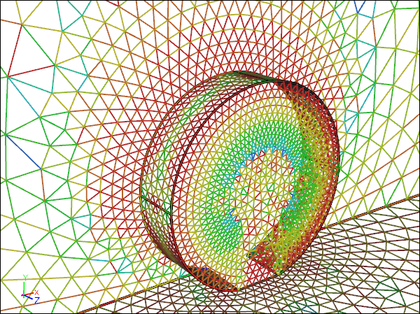
 CFD Mesh for a Faceted WheelNote spurious flat spots
While many CFD packages accept faceted geometry, it is usually inferior to analytic geometry because faceted geometry has:
- Limited discrete resolution of curvature (faceted assumes planar definition between points), whereas analytic definitions are continuous.
- Limited, if any, topology.
Representing curvature as a series of linear (planar) elements means that simulation tools downstream do not see the original continuous geometry and so produce compromised results on the wrong geometry.
 CFD Mesh for an Analytic WheelNote smooth variation around the wheel
CFD Mesh for a Faceted WheelNote flat spots and artificial corners around the wheel
 Rotating Wheel Pressure Coefficient (Cp) for an Analytic RepresentationNote smooth Cp variation around the wheel
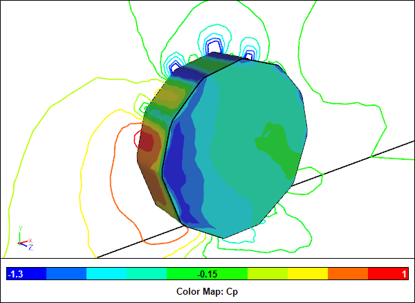 Rotating Wheel Pressure Coefficient (Cp) for a Faceted RepresentationNote spurious Cp peaks around the artificial corners on the wheel
It is often frustrating converting a faceted definition into a watertight solid/volume, because the original connectivity (topology) is lost in the conversion process from analytic to faceted. Resorting to splitting and grouping facets according to included angles and tolerance-based point comparisons to recover the original topology is less than ideal.
 Analytic Topology for a Cyclone
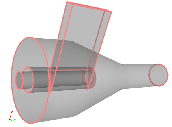 Faceted Topology for a CycloneNote missing edges compared to analytic topology
Sometimes there is no option but to use faceted geometry. For instance many scanned organic objects never had an analytic definition, so facets are your only recourse. Other times your choice of a faceted modeler (e.g., SketchUp) will dictate that your geometry is faceted. However, if you have control over your modeler software then it will pay dividends if you choose a CAD system that uses analytic geometry - which most do.
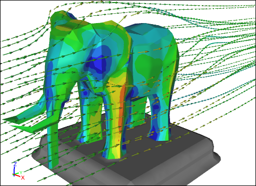 CFD Simulation Around an ElephantFaceted representation sourced from SketchUp
Exporting faceted geometry from a CAD system is nearly always a bad idea, given you could just as easily export the analytic geometry in a transfer format such as STEP or IGES. Exporting faceted geometry leaves you at the mercy of the CAD facet conversion process, which is typically optimized for visualization, i.e., a surface mesh in CFD speak, without much control over the quality of the facets.
 Flat Shaded Visualization FacetsNote individual facets are visible around curvature regions
Some CFD tools either only accept faceted geometry or perform an internal conversion process to facets prior to meshing. Here again, like in the CAD facet conversion process, you are at the mercy of a hidden surface meshing stage where the resolution of curvature is reduced to planar facets, thus losing the original continuous definition. The best CFD tools retain the analytic geometry, if supplied, and ensure that the final generated mesh points are located on the true analytic definition.
If you have taken great care to generate accurate geometry in your CAD system, then it is worth ensuring that the same analytic definition is the basis for your CFD simulations, rather than a potentially inferior faceted definition.
Feedback
Questions? Ideas? Problems?

Recent blog posts
- CFD Simulates Distant Past
- Background on the Caedium v6.0 Release
- Long-Necked Dinosaurs Succumb To CFD
- CFD Provides Insight Into Mystery Fossils
- Wind Turbine Design According to Insects
- Runners Discover Drafting
- Wind Tunnel and CFD Reveal Best Cycling Tuck
- Active Aerodynamics on the Lamborghini Huracán Performante
- Fluidic Logic
- Stonehenge Vortex Revealed as April Fools' Day Distortion Field
 Get our Blog feed