
Design for Simulation then Manufacture
Performing a Computational Fluid Dynamics (CFD) simulation on a detailed CAD model is no fun and, more importantly, it is often near useless. Why? Because given that an engineer has committed considerable time and effort to produce a detailed model ready for manufacture, I doubt they will be happy making additional model changes and the extensive rework that it will entail in response to the CFD results. Design for Manufacture (DFM) has been a successful and widely adopted strategy to reduce product manufacturing costs (bottom line improvement). However, such a focus on manufacturability in isolation from functional analysis and optimization (e.g., we can make a cheap airplane, but will it fly?) is missing a huge opportunity to provide enhanced functional capabilities for which customers are willing to pay a premium (top line improvement).
Rather than the Design for Manufacture mantra, I suggest a better approach is to adopt Design for Simulation, then Manufacture, where simulation could be any combination of stress analysis, CFD, etc.
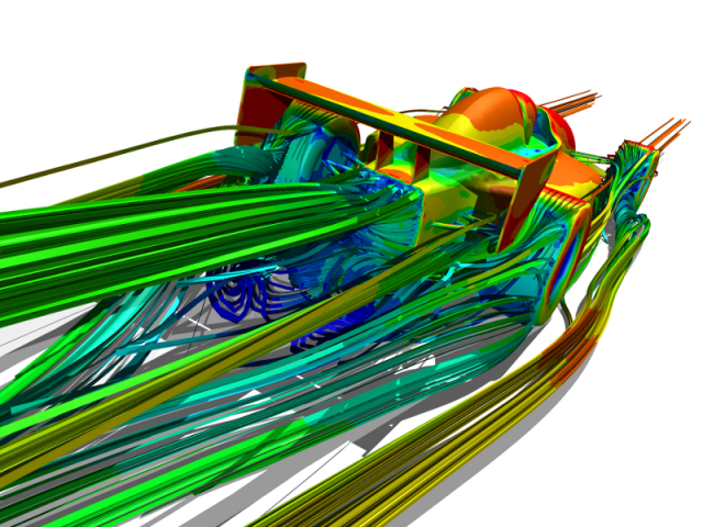 Open Wheel Race Car CFD Simulation
The practicalities of using a detailed CAD model as the basis for a CFD simulation are that the details get in the way of the big picture. Manufacturing details such as small holes, fillets, bolts, etc. usually have an insignificant effect on the overall flow characteristics, such as lift, drag, pressure drop, and heat transfer. However, including such details in a CFD simulation means you end up having to resolve them, which in turn means wasting precious mesh cells and increasing simulation turnaround times for virtually no incremental improvements in results accuracy. In addition, the resolution of such small-scale features in a simulation may also entail significant interactive fixing by an engineer to ensure a valid mesh. Now do you see what I mean by no fun?
During the initial concept design phase it is much easier and faster to keep the geometry as simple as possible while still representative of your product. Forget about manufacturing constraints, e.g., bolts, fillets. Also if possible keep major geometric features separate so that they can be easily moved or replaced without requiring major CAD rework.
Racecar Example
In the case of aerodynamic design of an open-wheel racecar, your initial concept model would represent the wheels, body, undertray (diffuser), rear and front wings. Ignore for now the mounts for the wings connecting them to the car body and ignore too the suspension that attaches the wheels to the car body. With this simple geometry setup you can freely move or modify the airfoils and body independently to find an optimal configuration, based on lift and drag values from the CFD simulation. Clearly to perform this initial concept analysis you don't need an elaborate CAD system, in fact a simple geometry creation tool should be more than adequate and better still if it's integrated directly into the CFD tool.
Often during the concept design phase it is worth considering focused CFD simulations on particular elements of the car in isolation. For instance investigating the front wing profile and ground clearance, or the rear wing multi-element arrangement can help serve as a baseline configuration for such elements prior to integration into the complete concept model outlined in the previous paragraph.
The next design phase would add some of the secondary features of the racecar likely to affect the aerodynamics, such as the airfoil mounts and the suspension, but still avoiding the minutia, such as bolts and fillets. Any subsequent geometry modifications during this phase are relatively minor so the added geometry will not overly constrain the changes you want to make in response to the CFD simulation results.
At some point you have to transition the concept design to detailed design in preparation for manufacture. There is still scope for CFD simulation to confirm your final design, but it is best performed just prior to the detailed design activity. As soon as the manufacturing constrains are added to the design, CFD simulations enter the no fun zone.
Once the detailed design for manufacture is complete, there is a good case for limited physical testing to validate the final functional characteristics, or why else commit to detailed design for manufacture? At some point you have to face reality, right?
Feedback
Questions? Ideas? Problems?

Recent blog posts
- CFD Simulates Distant Past
- Background on the Caedium v6.0 Release
- Long-Necked Dinosaurs Succumb To CFD
- CFD Provides Insight Into Mystery Fossils
- Wind Turbine Design According to Insects
- Runners Discover Drafting
- Wind Tunnel and CFD Reveal Best Cycling Tuck
- Active Aerodynamics on the Lamborghini Huracán Performante
- Fluidic Logic
- Stonehenge Vortex Revealed as April Fools' Day Distortion Field
 Get our Blog feed