
How to Fix Small Acute Angles for CFD
Small acute angles in your geometry, such as those found where a tangential surface meets a cylindrical surface, can lead to poor results from your Computational Fluid Dynamics (CFD) simulation. Keep reading to learn how to identify and remedy acute angles.
 Small Acute Angled Geometry FeatureProduces poor mesh elements
Acute angles are relatively easy to identify just by viewing the geometry. Wherever edges form tangents you will find acute angles.
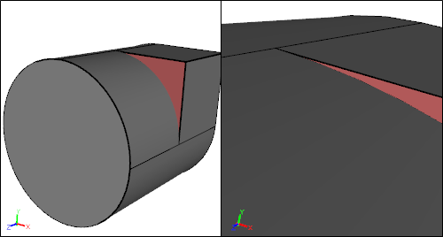 Small Acute Angled Geometry FeatureProduced by a tangential surface to a cylinder
Acute angles force mesh elements to mimic the same angle causing highly skewed elements.
Acute Angle Forces Creation of Poor Mesh ElementsE Ratio is a surface mesh metric ranging between 0 (bad) and 1 (best)
Trying to better resolve the angle with smaller elements usually makes the problem worse resulting in even higher element skewness.
 Smaller Mesh Sizing Creates Lower Quality Mesh ElementsSmaller element quality is lower at 0.069 compared to larger element quality of 0.096
If the edges that coalesce to form an acute angle are also feature edges (i.e., attached to faces angled at 135 degrees or less) then rather than simply combine (or join) faces to remove the edge you will need to locally modify the geometry near the edge junction.
Using the simple Boolean unite of a box and a cylinder as an example I'll demonstrate how to remove the pinnacle of an acute angle. First position a box at the tangent-edge junction.
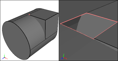
 Box Positioned At The Acute Angle
Next decompose (intersect and subtract) the acute angled face and its neighbor face with the box.
 Decompose Faces with Box
Retain the edges but delete the faces formed by the intersect during the decompose operation.
 Delete Faces Retaining Edges
With the retained edges create two new faces by lofting surfaces through the highlighted edges.
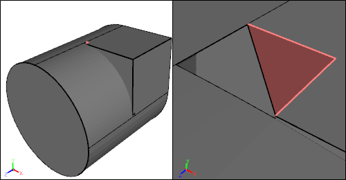 First Lofted FaceLoft edges highlighted in red
Lofting tends to be more reliable and predictable than stitching faces from edges.
 Second Lofted FaceLoft edges highlighted in red
Complete the procedure by stitching faces to form the water tight flow volume.
 Stitched Water Tight Flow Volume
While this procedure introduces a small edge that needs to be resolved with small mesh elements, it removes the more troublesome acute angle that lead to highly skewed mesh elements. Notice the remaining feature line that defines the intersection of the original cube with the cylinder is retained and resolved.
 Higher Quality Mesh Freed From Acute Angle Constraint
The lowest quality surface mesh metric for the new geometry is 0.48, which is significantly better than the original value of 0.096. Also the lowest metric value is no longer at the pinnacle of the acute angle.
Feedback
Questions? Ideas? Problems?

Recent blog posts
- CFD Simulates Distant Past
- Background on the Caedium v6.0 Release
- Long-Necked Dinosaurs Succumb To CFD
- CFD Provides Insight Into Mystery Fossils
- Wind Turbine Design According to Insects
- Runners Discover Drafting
- Wind Tunnel and CFD Reveal Best Cycling Tuck
- Active Aerodynamics on the Lamborghini Huracán Performante
- Fluidic Logic
- Stonehenge Vortex Revealed as April Fools' Day Distortion Field
 Get our Blog feed