
World Cup Stadium Aerodynamics with CFD
The 2014 FIFA World Cup is well underway and the final match to crown the world champions will be played in the Maracanã Stadium. The stadium was originally built to host the 1950 World Cup final, but with the stadium being the focal point for the current 2014 World Cup and the upcoming 2016 Olympics it was deemed that it needed a revamp. The most striking difference between the old and newly renovated stadium is the roof that now protects 95% of the seating from rain and provides better shade. The original roof only offered minimal rain protection and shade to a few rows of seats. However, it seems little air-time has been devoted to analyzing the wind characteristics of the playing area inside the stadium due to the different roof extents, especially when you consider how much attention the aerodynamics of the match ball have garnered. Rest easy though, Computational Fluid Dynamics (CFD) is here to help.
 Caedium CFD Simulation of a StadiumStreamlines
Geometry
After constructing an idealized (simple) version of the Maracanã Stadium I conducted a parameterized study varying the diameter of the hole in the roof. The roof is a tensioned membrane and therefore can be modeled as a double-sided face for CFD.
 Actual Maracanã Stadium with New RoofImage courtesy of Portal da Copa, Licença Creative Commons Atribuição 3.0 Brasil
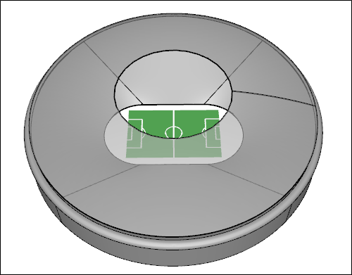 Idealized CFD Maracanã Stadium
Study
As a measure of the wind level in the playing area I constructed a volume extending from the pitch upwards 50 m towards the roof and recorded the volume weighted average of the velocity magnitude for each roof diameter.
 Field of Play VolumeShown in red
Based on pictures of both variants of the roof on the stadium I estimate that the old roof had a hole-to-roof diameter ratio of 0.67 and the new roof has a ratio of 0.42.
The onset free-stream velocity was set at 10 m/s parallel to the length of the pitch for all the CFD simulations.
Results
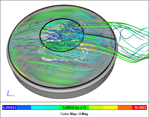
 Streamlines for Hole-to-Roof Ration = 1 (Open)
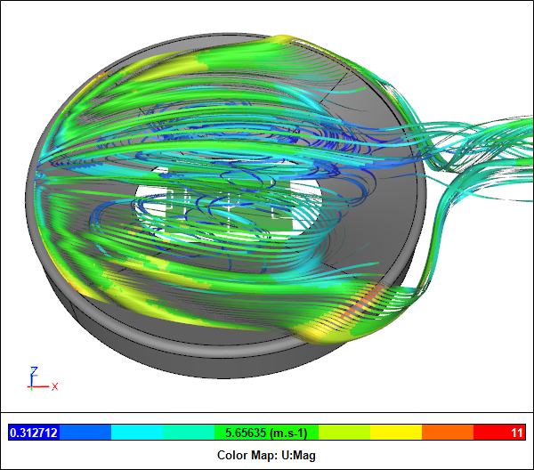
Streamlines for Hole-to-Roof Ration = 0.4
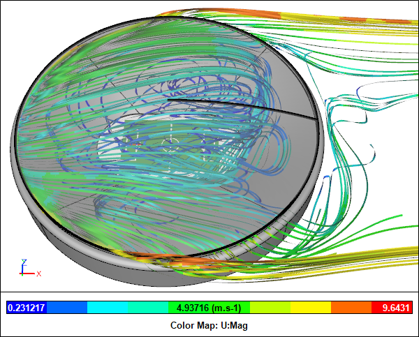 Streamlines for Hole-to-Roof Ration = 0 (Closed)
 Hole-to-Roof Diameter Ratio vs Average-to-Free-Stream Velocity Ratio
The hole-to-roof diameter ratio vs average-to-free-stream velocity ratio graph shows that varying the hole diameter from a full roof (0) to a totally open stadium (1) causes the average velocity within the field of play to vary within a relatively narrow band (0.16 - 0.32 x free stream wind velocity). The smaller the hole-to-roof ratio the lower the average velocity. Also, there appears to be plateaus at either extreme of the hole-to-roof ratio where increasing the ratio above 0.6 and reducing the ratio below 0.3 have little effect on the average velocity.
Conclusion
According to these results a smaller hole diameter results in a lower average velocity relative to the free-stream wind velocity. The revamped roof on the stadium with the smaller hole diameter compared to the original stadium's roof not only provides more rain protection and shade, but also ensures that the field of play is less prone to wind effects. Based on the old and new hole-to-roof ratios and these results I'd estimate about a 43% reduction in wind effects in the playing area. Everyone wins - you heard it here first!
Notes
The parameterized simulations were driven by a Python script in Caedium Professional using the incompressible, steady-state RANS solver with the k-omega turbulence model.
- Richard Smith's blog
- Login to post comments
Select Language
Free 30-Day Trials

Feedback
Questions? Ideas? Problems?

Recent blog posts
- CFD Simulates Distant Past
- Background on the Caedium v6.0 Release
- Long-Necked Dinosaurs Succumb To CFD
- CFD Provides Insight Into Mystery Fossils
- Wind Turbine Design According to Insects
- Runners Discover Drafting
- Wind Tunnel and CFD Reveal Best Cycling Tuck
- Active Aerodynamics on the Lamborghini Huracán Performante
- Fluidic Logic
- Stonehenge Vortex Revealed as April Fools' Day Distortion Field
 Get our Blog feed