
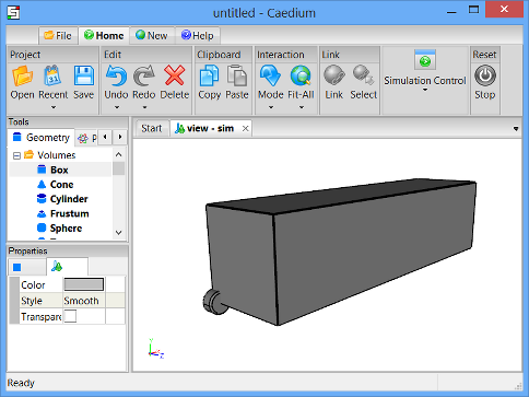
Wheel in a Box
Create a wheel by using the fillet tool on a cylinder. Then create a symmetric flow volume by subtracting the wheel from a box.

Goals
In this tutorial, you will learn how to:
- Create a cylinder and a box
- Fillet a face on a cylinder
- Translate a volume
- Subtract one volume from another
Assumptions
- You have activated the Caedium Builder add-on or Caedium Professional.
- You are familiar with Caedium essentials.
Create a Cylinder
Select the Geometry Tool Palette.
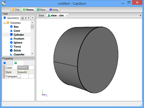
Select the Volumes->Cylinder tool. In the Properties Panel, set the Radius to 0.3 and set the Z Height to 0.3. Press Enter on the keyboard to apply the changes to the Properties Panel.

Drag and drop the Volumes->Cylinder tool onto the View Window (view). Select Done to create a cylinder (volume).
All geometry is created at the origin by default.
To shade all the faces in the simulation, right-click on the View Window background, double-click sim->Faces in the Select dialog, and then select Properties from the menu. In the Properties Panel, turn off the Transparent property.
Left-click-and-drag the mouse in the View Window until your view looks like that shown below.
Fillet a Face on the Cylinder
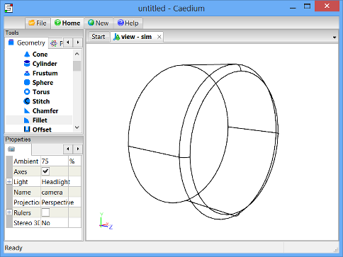
You are creating a symmetric model, so you need to fillet only one face on the cylinder to mimic a wheel.
Select the Volumes->Fillet tool. In the Properties Panel, set the Radius to 0.025.
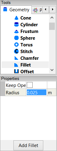
Drag and drop the Volumes->Fillet tool onto the planar circular face furthest from the origin of the cylinder (volume). Double-click the first face (face_3) in the Select dialog and select Done to create the wheel (volume_1).
Create a Box
Select the Volumes->Box tool. In the Properties Panel, set Lengths to [10 2.5 2.5]. Press Enter on the keyboard to apply the changes to the Properties Panel.
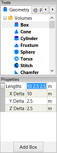
Drag and drop the Volumes->Box tool onto the View Window (view). Double click sim in the Select dialog and then select Done to create a box (volume_2).
To make picking easier, shade all the faces in the simulation. Right-click on the View Window background, double-click sim->Faces in the Select dialog, and then select Properties from the menu. In the Properties Panel, turn off the Transparent property to shade all faces.
In the Home Toolbar click the Fit-All button  to see all the geometry in the View Window.
Translate the Box
To translate the box (volume_1) to a new location in the View Window, select the Transforms->Translate tool. In the Properties Panel set Translate to [-3 -0.29 0.15] and press Enter on the keyboard to apply the changes.

Drag the Transforms->Translate tool and drop it directly onto a face of the box in the View Window. Select Done to translate the box.

Subtract the Wheel from the Box
Drag and drop the Booleans->Subtract tool directly onto a face of the box. Double-click volume_2 in the Select dialog to select the box. Select Select/Deselect from the menu, right-click on a face of the wheel (volume_1), and then double-click volume_1 in the Select dialog to select the cylinder. Select Done to subtract the cylinder from the box and create the final symmetric flow volume (volume_3).
Notes
The complete geometry created in this tutorial is available as a free download: wheel-in-box.brep (41 KB).
See the "Flow Over a Rotating Wheel with Moving Ground" tutorial for a flow simulation over the wheel.
- Login to post comments
Select Language
Free 30-Day Trials

Feedback
Questions? Ideas? Problems?

Comments
I've completed this tutorial
I've completed this tutorial and now I would like to do a similar thing but instead of the wheelshape I've imported a stl mesh.
The problem I got is that the stl mesh dont show up as a volume so I cant do the boolean subtract part.
How would I do this correctly (getting the stl mesh as a volume)?
The mesh is "watertight", no glitches between triangles or so.
STL is not currently supported in a volume mesh
You can't currently use an STL file in a volume mesh. Consider using STEP (.stp) instead if you have the option.
Ok thanks! STL is the only
Ok thanks! STL is the only mesh format that can be used in boolean operations?
I presume you mean STEP
I presume you mean STEP (.stp). STEP is not a mesh format it is a geometry format (analytic, NURBS) typically used by CAD systems. For more details try "Geometry Exchange."