
5 Tips for CFD Flow Volume Creation
Configuring a flow volume for Computational Fluid Dynamics (CFD) is often the most difficult task during the simulation process. Follow these 5 tips to make your CFD flow volume creation less painful.
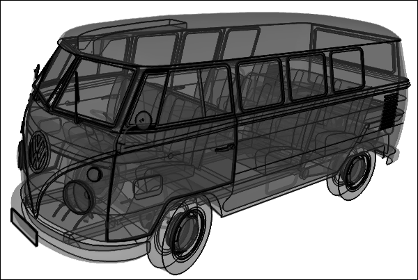 3D Model With Too Much Detail for CFD
1. Use a CAD system to create flow volumes
A consistent solid model is referred to as manifold when all edges are connected to exactly 2 faces. Most CAD systems support and encourage the creation of manifold models, but their creation is not mandatory.
 3D Model With Reduced Detail for CFD
Often it is easier to create the flow volume explicitly in a CAD system and remove features that are not necessary for CFD or, better still, create simplified geometry for analysis during the concept design phase of a project.
2. Remove slivers
Sometimes geometry construction produces 'slivers' - small narrow faces - that can cause problems for meshing tools.
 Sliver Face (Red) on a Model
Having identified a sliver it can often be removed by simply joining it with a larger neighboring face or subtracting/adding another solid (e.g., a cylinder) that subsumes it.
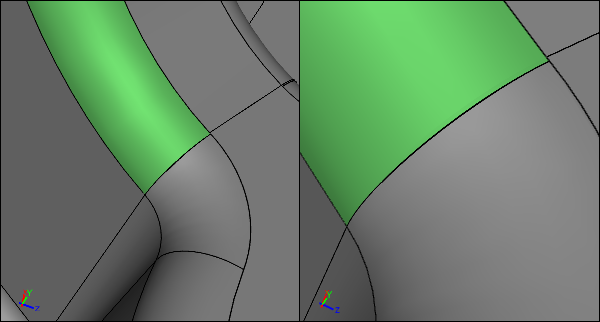 Sliver After Joining with Larger Neighbor (Green)
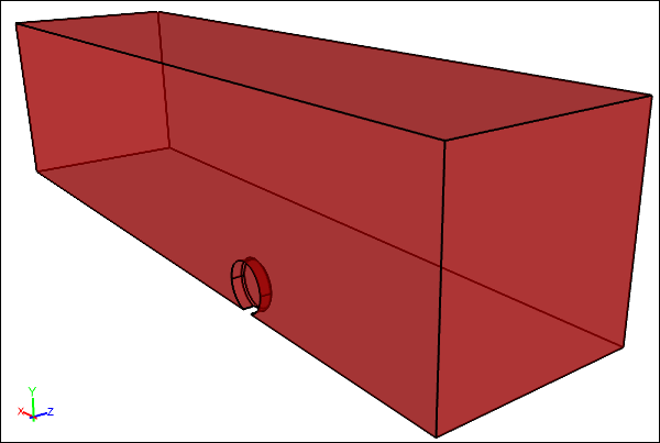
3. Connect edges, stitch faces, and subtract to form a flow volume
When a non-manifold model is the basis for an external CFD analysis, the first task is to make it manifold (except for membrane simulations) - usually by connecting edges and/or stitching the faces to form a solid.
 Wheel Solid and Outer Box Solid Before Subtract Boolean
With the object defined as a solid it can now be subtracted from a larger outer boundary box to form the final flow volume for an external flow simulation. Sometimes due to the complexity of a model you might also have to stitch the final flow volume from faces instead of subtract one solid from another.
 Wheel Solid and Outer Box Solid After Subtract Boolean
4. Add inlet, outlet, and symmetry faces for internal flow volumes
For an internal CFD analysis there may be a need to create new faces to represent the inlet, the outlet, and often the symmetry planes. Then you need to stitch the faces together with the original faces that will be in contact with the fluid.
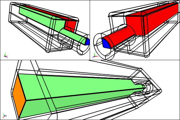 Internal Flow VolumeNew Inlet (Blue), Outlet (Orange), and Symmetry (Green) Faces Stitched With Existing Faces (Red)
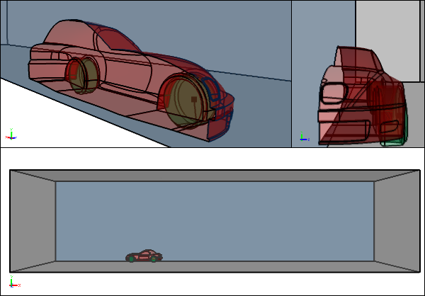
5. Keep inlets and outlets away from velocity and pressure gradients
Inlets need to be positioned well upstream from velocity and pressure gradients, and similarly outlets need to positioned well downstream from velocity and pressure gradients. This requirement may mean extending the flow volume beyond its original bounds.
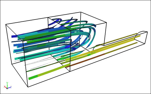 Poorly Positioned OutletStraddling a recirculation zone
For example, the outlet downstream of a valve needs to extend well past the valve exit. Poorly positioned inlets and outlets often prevent simulation convergence and produce misleading flow results.
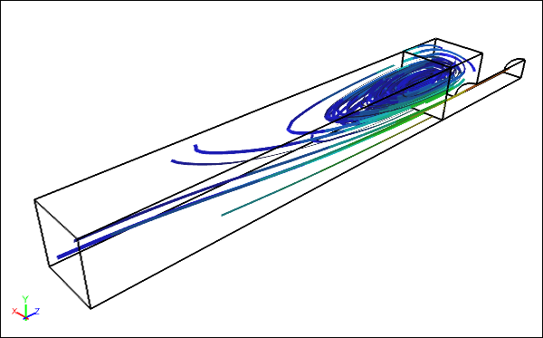 Better Positioned OutletDownstream away from the recirculation zone
Feedback
Questions? Ideas? Problems?

Recent blog posts
- CFD Simulates Distant Past
- Background on the Caedium v6.0 Release
- Long-Necked Dinosaurs Succumb To CFD
- CFD Provides Insight Into Mystery Fossils
- Wind Turbine Design According to Insects
- Runners Discover Drafting
- Wind Tunnel and CFD Reveal Best Cycling Tuck
- Active Aerodynamics on the Lamborghini Huracán Performante
- Fluidic Logic
- Stonehenge Vortex Revealed as April Fools' Day Distortion Field
 Get our Blog feed