
Heat Sink
Create a symmetrical multi-volume domain for a Conjugate Heat Transfer (CHT) simulation of a heat sink.
Goals
In this tutorial, you will learn how to:
- Create a coupled multi-volume domain
- Create multiple boxes
- Translate objects
- Subtract volumes
- Decompose volumes
- Link faces
Assumptions
- You have activated the Caedium Builder add-on or Caedium Professional.
- You are familiar with Caedium essentials.
Create the Heat Sink Blank as a Box
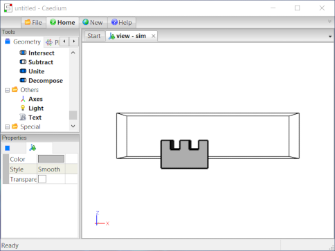
This box is the blank from which we will cut (subtract) the fins of the heat sink.
Select the Geometry Tool Palette.
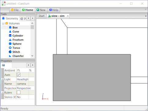
Select the Volumes->Box tool. In the Properties Panel, set Lengths to [0.05 0.035 0.03]. Press Enter on the keyboard to apply the changes to the Properties Panel.
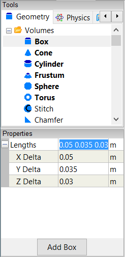
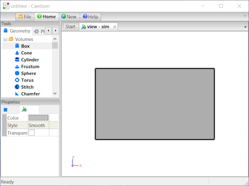
Drag and drop the Volumes->Box tool onto the View Window (view). Select Done to create a box (volume).
All geometry is created at the origin by default.
To shade the faces of the box, right-click on an edge of the volume, double-click volume->Faces, and then select Properties from the menu. In the Properties Panel, turn off the Transparent property.
Translate the Heat Sink Blank
To translate the box (volume) to a new location in the View Window, select the Transforms->Translate tool. In the Properties Panel set Translate to [0 -0.01 -0.01] and press Enter on the keyboard to apply the changes.
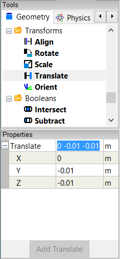
Drag the Transforms->Translate tool and drop it directly onto the box in the View Window. Select Done to translate the box.
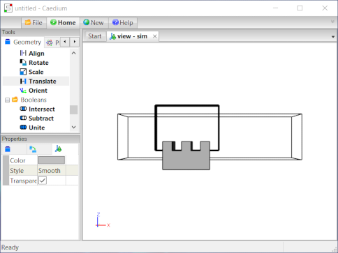
Create and Position the Outer Boundary
This box is the outer boundary of the flow domain that will incorporate the heat sink.
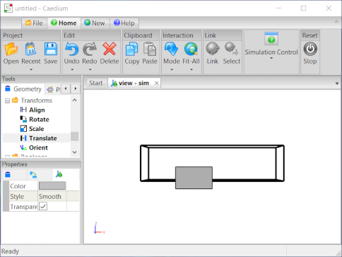
Select the Volumes->Box tool. In the Properties Panel, set Lengths to [0.2 0.05 0.05]. Press Enter on the keyboard to apply the changes to the Properties Panel. Drag and drop the Volumes->Box tool onto the View Window. Double click sim in the Select dialog and then select Done to create a box (volume_1).
To translate the outer boundary (volume_1) to a new location in the View Window, select the Transforms->Translate tool. In the Properties Panel set Translate to [-0.05 0 0] and press Enter on the keyboard to apply the changes. Drag the Transforms->Translate tool and drop it directly onto an edge of the outer boundary (volume_1) in the View Window. Select Done to translate the outer boundary.
In the Home Toolbar click the Fit-All button  to see all the geometry in the View Window.
Create and Position the Y-Direction Fins
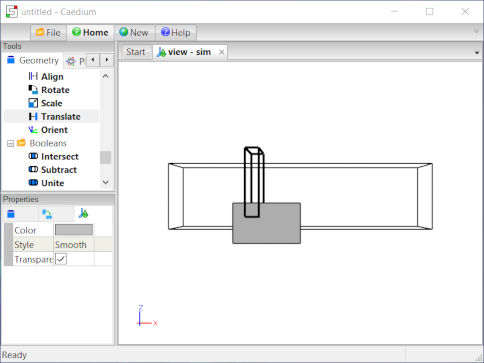
Select the Volumes->Box tool. In the Properties Panel, set Lengths to [0.01 0.05 0.05]. Press Enter on the keyboard to apply the changes to the Properties Panel. Drag and drop the Volumes->Box tool onto the View Window. Double click sim in the Select dialog and then select Done to create a box (volume_2).
To translate the box (volume_2) to a new location in the View Window, select the Transforms->Translate tool. In the Properties Panel set Translate to [0.01 -0.02 0.01] and press Enter on the keyboard to apply the changes. Drag the Transforms->Translate tool and drop it directly onto an edge of the box (volume_2) in the View Window. Select Done to translate the box (volume_2).
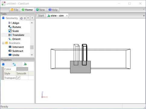
Right-click on an edge of the box (volume_2) in the View Window. Double-click volume_2 in the Select dialog to select the box, and select the Copy option.
In the Home Toolbar click Paste  to paste a copy of the box (volume_2) at the same location as the original.
To translate the box copy (volume_3), select the Transforms->Translate tool. In the Properties Panel set Translate to [0.02 0 0]. Drag the Transforms->Translate tool and drop it directly onto an edge of the box copy in the View Window. Double-click volume_3 in the Select dialog to select the box copy and select Done to translate the box copy.
Subtract Y-Direction Fins
Drag and drop the Booleans->Subtract tool directly onto a shaded face of the heat sink blank. Double-click volume in the Select dialog to select the heat sink blank. Select Select/Deselect from the menu, right-click on an edge of the first Y-direction fin box. Double-click volume_2 to select the first Y-direction fin box. Select Select/Deselect from the menu, right-click on an edge of the second Y-direction fin box. Double-click volume_3 to select the second Y-direction fin box. Select Done to produce the heat sink with Y-direction fins (volume_4).
To shade the faces of the resultant volume, right-click on an edge of the volume, double-click volume_4->Faces, and then select Properties from the menu. In the Properties Panel, turn off the Transparent property.
Create and Position the X-Direction Fins
Select the Volumes->Box tool. In the Properties Panel, set Lengths to [0.07 0.01 0.05]. Press Enter on the keyboard to apply the changes to the Properties Panel. Drag and drop the Volumes->Box tool onto the View Window. Double click sim in the Select dialog and then select Done to create a box (volume_5).
To translate the box (volume_5) to a new location in the View Window, select the Transforms->Translate tool. In the Properties Panel set Translate to [-0.01 0.005 0.01] and press Enter on the keyboard to apply the changes. Drag the Transforms->Translate tool and drop it directly onto an edge of the box (volume_5) in the View Window. Select Done to translate the box (volume_5).
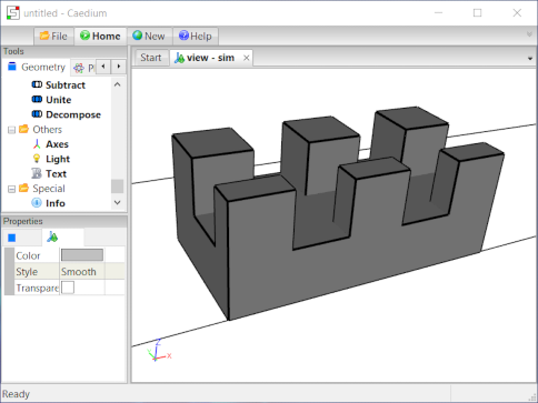
Subtract X-Direction Fins
Drag and drop the Booleans->Subtract tool directly onto a shaded face of the heat sink with Y-direction fins. Double-click volume_4 in the Select dialog to select the heat sink with Y-direction fins. Select Select/Deselect from the menu, right-click on an edge of the X-direction fin box. Double-click volume_5 to select the X-direction fin box. Select Done to produce the heat sink with the complete fins (volume_6).
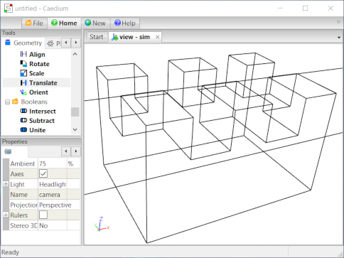
Create Multi-Volume Simulation Domain
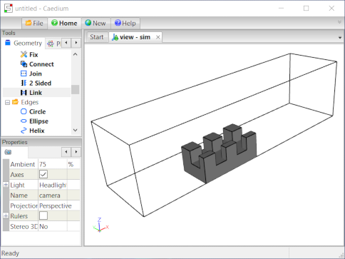
Drag and drop the Booleans->Decompose tool directly onto an edge of the outer boundary box. Double-click volume_1 in the Select dialog to select the outer boundary box. Select Select/Deselect from the menu, right-click on an edge of the complete heat sink. Double-click volume_6 to select the complete heat sink. Select Done to produce the two volume domain, where the fluid region (volume_7) encloses the solid heat sink region (volume_8).
To shade the faces of the heat sink, right-click on an edge of the heat sink, double-click volume_8->Faces, and then select Properties from the menu. In the Properties Panel, turn off the Transparent property.
Link the Faces
To prepare the multi-volume domain for a CHT simulation we need to couple the fluid faces with the coincident solid faces.
Drag and drop the Faces->Link tool onto the background of the View Window and double click sim->Faces in the Select dialog. Select Done to link the coincident faces between the two volumes that will propagate the heat flux coupling between the heat sink and the surrounding air.
Notes
The complete geometry created in this tutorial is available as a free download at heat-sink.sym.
See the "Conjugate Heat Transfer for a Heat Sink" tutorial for a flow simulation that uses this geometry.
Feedback
Questions? Ideas? Problems?
